Amplitude Processing and Onsite Early Warning
In earthquake early warning (EEW) systems speed matters and is of highest priority along with the reliability of the measured or predicted parameters. Instead of measuring amplitudes and predicting parameters in a data center after the location of a seismic event is available, the most relevant parameters can be measured during phase detection before a hypocenter is available. The amplitude measurements can even be made at the station allowing for a rapid onsite early warning system.
For measuring these amplitudes the sigma package provides the plugins for application by external modules outside of AUTOSIGMA or SIGMA:
sigmaamps,
sigmaampsp1,
sigmaampsp2.
If these plugins are added to the SeisComP modules scautopick or scamp and available amplitudes are configured, the modules measure configured amplitudes from waveforms. The amplitudes include types which are typically required for
Onsite early warning,
Earthquake Early Warning (EEW),
Strong motion earthquake analysis,
Seismic engineering purposes.
Concept
The plugins measure the amplitudes of a particular type in a specific time window on the respective components of the amplitude type. One plugin can take exactly one configuration for one amplitude type. In order to facilitate the computation of the same amplitude type with up to three different set of parameters, e.g. different time windows around P and S waves, the plugin exists three times in the same form with the different names.
Amplitude types
The plugins compute values for the following quantities as SeisComP amplitude objects of different kind.
Available amplitudes are:
CAV: Cumulative absolute velocity,
CI: Characteristic intensity,
IA05: Arias intensity at 5%,
IA25: Arias intensity at 25%,
IA50: Arias intensity at 50%,
IA75: Arias intensity at 75%,
IA95: Arias intensity at 95%,
IAD05-95: Duration (5%-95%),
IAD25-75: Duration (25%-75%),
pdPvR:
 ratio. The actual values are given
by pgd and pgv amplitudes which must be configured.
ratio. The actual values are given
by pgd and pgv amplitudes which must be configured.Note
snrPd and pdPvR are implemented according to Caruso et al. [32] without the threshold check suggested therein. The check can be made by an external script after reading the amplitudes.
For computing snrPd and pdPvR identical time windows for PGD and PGV amplitudes must be configured to be complient with Caruso et al. [32].
The incrementation of the time window for measuring PGD and PGV (e.g. 1 s, 2 s, 3 s) can be realized by running 3 the different plugins in parallel with their specific configuration of the time windows. The sections Configuration parameters and Setup provide examples.
PGA: Peak ground acceleration, PGA,
PGD: Peak ground disaplacement, PGD,
PGV: Peak ground velocity, PGV,
PSA_0_3: Pseudo Spectral Amplitude measured at 0.3 s period,
PSA_1_0: Pseudo Spectral Amplitude measured at 1.0 s period,
PSA_3_0: Pseudo Spectral Amplitude measured at 3.0 s period,
SED: Specific energy density,
snrPd: Signal-to-Noise ratio of PGD in the data time window after the trigger and the PGD within the noise time window before (
 ):
):
 is the measured PGD amplitude and
is PGD measured in the noise time window.
is the measured PGD amplitude and
is PGD measured in the noise time window.Tm: Mean period,
Tp: Predominant period.
Data streams and time windows
The amplitude can be measured on four different data streams, the stream components:
v: vertical component,
h1: first horizontal component,
h2: second horizontal component,
h: the sample-wise vector sum of the horizontal components:
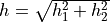 ,
,l: the sample-wise vector sum of the vertical and the horizontal components:
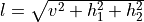 .
.
The time windows for computing amplitudes are relative to a reference time: * either a pick time or * a predicted phase onset.
Generally a noise and a signal window are considered. While the noise window typically starts and ends before the reference time, the signal window is around or after it. Reference time and window parameters are configurable per component. Read Configuration parameters for more details.
Amplitude types
The names of the amplitude types start with the name of the measured amplitude followed by the component. When measured with the sigmaamps plugin, no further specification is made:
[type][_component]
When computed with sigmaampsp1 or sigmaampsp2, _p1 or _p2 is appended, respectively.
Examples:
PGA computed by the sigmaamps plugin on the vertical (‘v’) or the first horizontal (‘h1’) component:
PGA_v
PGA_h1
PGA computed by the sigmaampsp1 or the sigmaampsp2 the plugin on the vertical (‘v’) or the first horizontal (‘h1’) component:
PGA_v_p1
PGA_h1_p1
PGA_v_p2
PGA_h1_p2
The measureable amplitudes types can be selected and configured by their names in other modules, e.g. scamp [10] or scolv [12] when the plugins are loaded. SIGMA amplitudes in XML files or in the database can be identified by these names.
Configuration parameters
Each amplitude type takes up to 8 parameters defining the time windows for computing the amplitudes and the waveform filtering.
Reference phase types for calculating time windows (optional, only used considered by scamp):
phaseStart: phase type defining the reference for the start of the time window, e.g.
phaseStart = P
phaseEnd: phase type defining the reference for the end of the time window, e.g.
phaseEnd = S
Note
The parameters
phaseStartandphaseEndare optional configuration parameters. They are used for prediction of arrival times of the configured phase types. They are only considered when computing the amplitudes by scamp where origins exist and the arrival times of P and S waves can be predicted. IfphaseStartorphaseEndare not set, the respective time-window parameters are relative to the pick time.Phase-type or pick-related time windows:
noiseBegin: start of the noise window relative to phaseStart or pick time. Default:
noiseBegin = -8
noiseEnd: end of the noise window relative to phaseStart or pick time. Default:
noiseEnd = -4
signalBegin: start of the noise window relative to phaseStart or pick time. Default:
signalBegin = -4
signalEnd: end of the noise window relative to phaseEnd or pick time. Default:
signalEnd = 4
Note
The default values apply if the parameter is not explicitly configured.
The noise time window parameters are used to compute the SNR which is written to the resulting amplitude.
Filter parameters for band-pass filtering. Positive values of frequencies refer to frequencies in units of Hz (1/s, not angular frequency!). Negative values refer to the fraction of the Nyquist frequency:
loFilterFreq: lower cut-off frequency. Example setting the frequency to 1 Hz:
loFilterFreq = 1
hiFilterFreq: upper cut-off frequency. Example setting the frequency to 80% of the Nyquist frequency:
highFilterFreq = -0.8
order: order of the Butterworth filter frequency. Default:
order = 4
Note
The filter frequency parameters are optional. If not set, no filtering is applied.
The actual configuration parameters for the sigma amplitudes are currently NOT configurable in the global bindings as other amplitude types. Instead, the alternative configuration in the global configuration can be used. It takes the structure
module.trunk.global.amplitudes.[name].[parameter] = [value]
where [name], [parameter] and [value] are to be replaced by actual values.
While the filter parameters are set to values common for all plugin amplitude parameters, e.g.
module.trunk.global.amplitudes.sigma.loFilterFreq = -loFF-
module.trunk.global.amplitudes.sigma.hiFilterFreq = -hiFF-
module.trunk.global.amplitudes.sigma.order = -order-
the time windows are configured for each amplitude type individually, e.g. for the amplitude type I05_v:
module.trunk.global.amplitudes.I05_v.phaseStart = -P-
module.trunk.global.amplitudes.I05_v.phaseEnd = -S-
module.trunk.global.amplitudes.I05_v.noiseBegin = -noiseBegin-
module.trunk.global.amplitudes.I05_v.noiseEnd = -noiseEnd-
module.trunk.global.amplitudes.I05_v.signalBegin = -signalBegin-
module.trunk.global.amplitudes.I05_v.signalEnd = -signalEnd-
where the values enclosed by “-” are to be replaced in the configuration by actual values.
Setup
The configuration of the amplitude computation requires the steps set out below. Make all configurations for the considered modules either in the
Global module configuration (
global.cfg) orModule configurations of scautopick (
scautopick.cfg) or scamp (scamp.cfg).
Plugins selection: Add the plugin names to the list of loaded plugins in
plugins, e.g.plugins = ${plugins}, sigmaamps, sigmaampsp1, sigmaampsp2
Choose amplitude names: Add the amplitude names to be calculated by scautopick or scamp and the respective plugin and component, e.g., for the sigmaamps plugin:
amplitudes = IA05_v, IA25_v, IA50_v, IA75_v, IA95_v, CI_v, SED_v,\
  CAV_v, Tp_v, Tm_v, PGA_v, PGV_v, PGD_v, pdPvR_v,\
  IAD05-95_v, IAD25-75_v, PSA_0_3_v, PSA_1_0_v, PSA_3_0_v,\
  SED_v, snrPd_v, Tm_v, Tp_v,\
  IA05_h1, IA25_h1, IA50_h1, IA75_h1, IA95_h1, CI_h1, SED_h1,\
  CAV_h1, Tp_h1, Tm_h1, PGA_h1, PGV_h1, PGD_h1, pdPvR_h1,\
  IAD05-95_h1, IAD25-75_h1, PSA_0_3_h1, PSA_1_0_h1, PSA_3_0_h1,\
  SED_h1, snrPd_h1, Tm_h1, Tp_h1,\
  IA05_h2, IA25_h2, IA50_h2, IA75_h2, IA95_h2, CI_h2, SED_h2,\
  CAV_h2, Tp_h2, Tm_h2, PGA_h2, PGV_h2, PGD_h2, pdPvR_h2,\
  IAD05-95_h2, IAD25-75_h2, PSA_0_3_h2, PSA_1_0_h2, PSA_3_0_h2,\
  SED_h2, snrPd_h2, Tm_h2, Tp_h2,\
  IA05_h, IA25_h, IA50_h, IA75_h, IA95_h, CI_h, SED_h,\
  CAV_h, Tp_h, Tm_h, PGA_h, PGV_h, PGD_h, pdPvR_h,\
  IAD05-95_h, IAD25-75_h, PSA_0_3_h, PSA_1_0_h, PSA_3_0_h,\
  SED_h, snrPd_h, Tm_h, Tp_h,\
  IA05_l, IA25_l, IA50_l, IA75_l, IA95_l, CI_l, SED_l,\
  CAV_l, Tp_l, Tm_l, PGA_l, PGV_l, PGD_l, pdPvR_l,\
  IAD05-95_l, IAD25-75_l, PSA_0_3_l, PSA_1_0_l, PSA_3_0_l,\
  SED_l, snrPd_l, Tm_l, Tp_l
For measuring amplitudes with the sigmaampsp1 and sigmaampsp2 plugins add the plugins to
pluginsand _p1 and _p2 to the names, respectively.Hint
The list of amplitude names is long and may be incompletely documented. To see a complete list, simply add the plugins to scolv and re-compute magnitudes from the scolv Location tab. When prompted to select the types you may read the amplitude names.
Warning
The names of amplitude types are case sensitive and may not be fully consistent with names used in scientific literature.
Configure the amplitude parameters: Add the set of configuration parameters for each configured amplitude type.
Example configuration for the amplitude type pga_v, time window parameters are related to actual pick times:
module.trunk.global.amplitudes.sigma.loFilterFreq = 2
module.trunk.global.amplitudes.sigma.hiFilterFreq = 6
module.trunk.global.amplitudes.sigma.order = 4

module.trunk.global.amplitudes.PGA_v.noiseBegin = -8
module.trunk.global.amplitudes.PGA_v.noiseEnd = -4
module.trunk.global.amplitudes.PGA_v.signalBegin = -4
module.trunk.global.amplitudes.PGA_v.signalEnd = 4
Example configuration for the amplitude type PGA_l_p2, time window parameters are related to predicted arrival times of the first arrival P phase. No filtering is applied:
module.trunk.global.amplitudes.PGA_l_p2.phaseStart = P
module.trunk.global.amplitudes.PGA_l_p2.phaseEnd = P

module.trunk.global.amplitudes.PGA_l_p2.noiseBegin = -8
module.trunk.global.amplitudes.PGA_l_p2.noiseEnd = -4
module.trunk.global.amplitudes.PGA_l_p2.signalBegin = -4
module.trunk.global.amplitudes.PGA_l_p2.signalEnd = 4
Repeat the configuration for all amplitude types selected in
amplitudes. Default values apply for amplitudes and parameters without a configuration.For measuring some amplitudes by default with scolv, add the amplitude types to the parameter magnitudes in the scolv module configuration (
scolv.cfg).
Application
The plugins and the amplitude parameters must be configured in the respective module configuration.
Measure the amplitudes in multiple ways:
Run scautopick or scamp in real time or in non-real-time XML-based playbacks where the created XML files contain the amplitudes among all other parameters.
Examples of non-real-time XML-based playbacks:
For scautopick simply provide the waveforms:
$ scautopick --ep --playback -I [waveform data source] -d [database] > picks.xml
For scamp: provide the waveforms and the Origins with Arrivals and Picks in
origins.xml:$ scamp --ep origins.xml -I [waveform data source] -d [database] > amplitudes.xml
Measure amplitudes interactively in scolv: Click on the button ‘Compute Magnitudes’ in the scolv Location tab and choose an amplituds type.
Read the amplitude values from the created XML files or from the database.
Results
The computed values are written to amplitude objects which can be found in the database or the XML files.
Example for IA05_v and CAV_v amplitudes computed by the plugins sigmaamps and sigmaampsp2, respectively:
<?xml version="1.0" encoding="UTF-8"?>
<seiscomp xmlns="http://geofon.gfz-potsdam.de/ns/seiscomp3-schema/0.11" version="0.11">
  <EventParameters>
     ...
     <amplitude publicID="Amplitude/20200824082953.802835.11139">
       <type>IA05_v</type>
       <amplitude>
         <value>0.04988864196</value>
       </amplitude>
       <timeWindow>
         <reference>2020-08-01T11:00:00.000000Z</reference>
         <begin>-4</begin>
         <end>4</end>
       </timeWindow>
       <snr>45.57455237</snr>
       <pickID>20000621.005250.79-GR.CLL..BHZ</pickID>
       <waveformID networkCode="GR" stationCode="CLL" channelCode="BHE"/>
       <creationInfo>
         <agencyID>gempa</agencyID>
         <author>scamp@localhost</author>
         <creationTime>2020-08-01T12:00:00.000000Z</creationTime>
       </creationInfo>
     </amplitude>
     ...
     <amplitude publicID="Amplitude/20200824082953.829365.11156">
       <type>CAV_v_p2</type>
       <amplitude>
         <value>0.2932203282</value>
       </amplitude>
       <timeWindow>
         <reference>2020-08-01T11:00:00.000000Z</reference>
         <begin>-4</begin>
         <end>4</end>
       </timeWindow>
       <snr>45.57455237</snr>
       <pickID>20000621.005250.79-GR.CLL..BHZ</pickID>
       <waveformID networkCode="GR" stationCode="CLL" channelCode="BHE"/>
       <creationInfo>
         <agencyID>gempa</agencyID>
         <author>scamp@localhost</author>
         <creationTime>2020-08-01T12:00:00.000000Z</creationTime>
       </creationInfo>
     </amplitude>
     ...
   </EventParameters>
</seiscomp>